Audit Methodology & Datasheet Verification
Known facts
Assessments are based entirely on published manufacturer datasheets, seller resolution listings, and verified customer transaction feedback.
No hands-on hardware testing or independent laboratory bench trials were conducted for this comparison.
Analysis
Marketing figures often advertise interpolated software resolution or LCD panel counts rather than raw detector matrix size.
Budget microbolometers optimized for broad building envelopes exhibit optical and sensitivity trade-offs when applied to circuit boards.
Uncertainties
True raw sensor NETD sensitivity ratings and exact focal constraints are frequently omitted from vendor listings.
Native Sensor Resolution Versus Display Panel Upscaling
Printed circuit board troubleshooting requires thermal detection tools capable of pinpointing microscopic electrical faults, excessive trace resistance, and shorted components. When an unmetered short circuit occurs on a power rail, the offending semiconductor, ceramic capacitor, or voltage regulator dissipates current as parasitic thermal energy.
A recurring challenge in marketplace listings is the conflation of physical microbolometer sensor resolution with display screen dimensions. Titles frequently highlight figures like 320x240 or ISR240x240. For delicate diagnostics, native detector pixels determine whether adjacent component pins produce distinct thermal profiles or blur into an unresolved hotspot. Upscaling smooths visual presentation but adds no genuine radiometric measurement points.
Core Bench Findings
Native Spatial Density
True hardware sensor resolution defines thermal separation between surface-mount traces; software upscaling cannot create new radiometric points.
Thermal Span Trade-Off
Wide measurement spans up to 550°C prioritize thermal ceiling over low-temperature Kelvin gradient contrast needed for low-power logic boards.
Dynamic Transient Logging
Onboard video recording commands a significant price premium but is necessary to capture momentary power-on short-circuit heat blooms.
Hardware Specifications & Diagnostic Profiles
| Product | Thermal Imager | Advertised Resolution / Optics | Stated Scope & Features | Catalog Price (USD) |
|---|---|---|---|---|
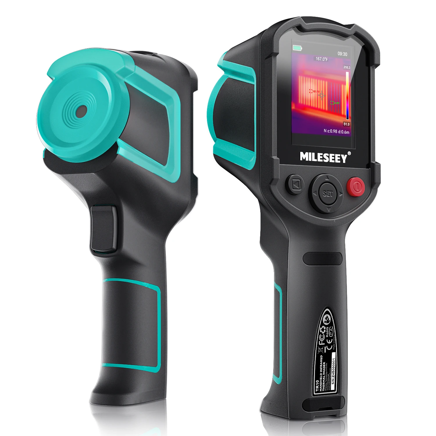
| Mileseey Infrared Thermal Camera TR10 TR256i Resolution… | Mileseey TR10 / TR256i | 192*256 IR Resolution | Mobile phone logic board repair & leak detection | $142.84 |
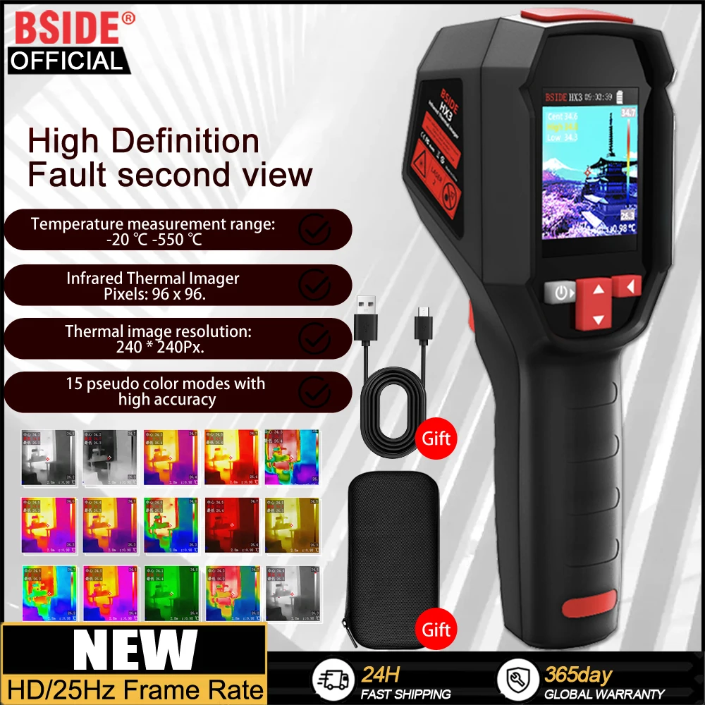
| BSIDE Handheld Thermal Imaging Camera Industrial HX3 -20-550C… | BSIDE HX3 | HD Resolution Handheld | -20°C to 550°C range, industrial casing | $112.74 |
| TOOLTOP ET14C 2.8inch Thermal Imager 25Hz Home Thermal imaging… | TOOLTOP ET14C | ISR240x240, 2.8-inch Display | 25Hz refresh rate, integrated bench stand | $125.12 |
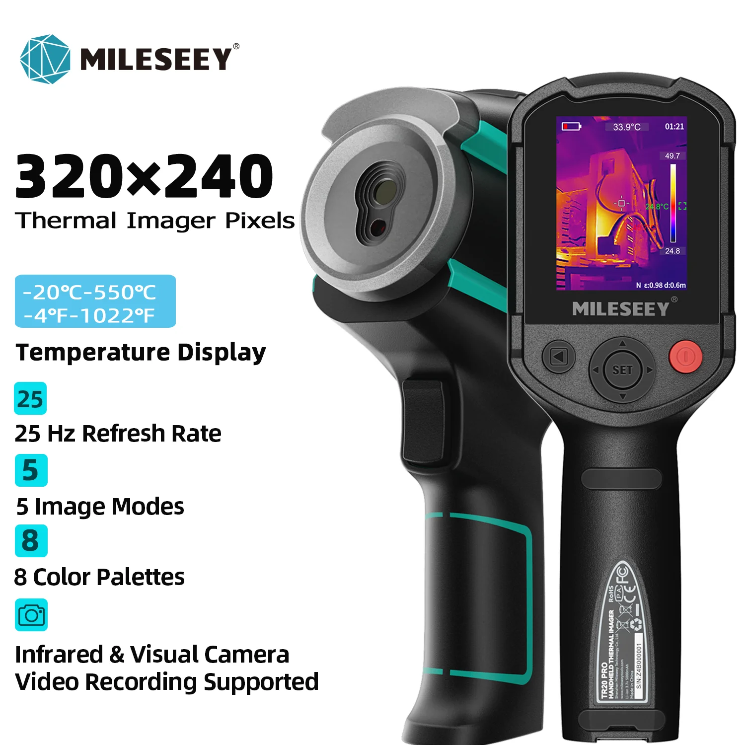
| MILESEEY TR256E /B Upgraded Thermal Imager 320x240 Thermal… | MILESEEY TR256E / TR256B | 320x240 Display Title Format | Onboard video recording for thermal event logging | $257.68 |
| BSIDE Handheld Thermal Imaging Camera 240X240 Temperature Meter… | BSIDE 240X240 Handheld | 240X240 Temperature Meter | Standalone automotive, pipeline, and PCB checks | $120.65 |


Workflow Balance: Specialized Resolution vs. Multi-Trade Utility
Pros
- 192*256 resolution units provide dense thermal mapping to discern adjacent surface-mount parts without severe pixel blending.
- Integrated bench mounts and 25Hz refresh rates allow stable real-time monitoring while guiding probes across live circuits.
- Broad temperature measurement ranges up to 550°C accommodate switched-mode transformers and high-voltage power components.
Cons
- Fixed-focus optics calibrated for multi-trade distances require careful manual positioning when focusing on sub-millimeter board traces.
- Extended thermal ranges reduce low-differential sensitivity, making faint logic-rail anomalies harder to isolate.
- Integrated video logging features introduce a steep price increase compared to snapshot-only diagnostic instruments.
Diagnostic Procurement Audit
- Audit native thermal sensor arrayVerify physical detector dimensions rather than relying on upscaled display panel pixel specifications.
- Examine refresh rate requirementsConfirm 25Hz operation if live probing is required to prevent visual lag while inspecting powered traces.
- Assess operational temperature spanSelect extended spans like -20°C to 550°C only if troubleshooting power supplies or industrial drives.
- Evaluate transient capture needsDetermine whether video recording is essential to capture brief power-up heating events before thermal stabilization.
Procurement Decision Architecture
Select the Mileseey TR10 / TR256i for fine-pitch logic board repair, or the TOOLTOP ET14C when hands-free benchtop monitoring at 25Hz is the operational priority.
High native microbolometer density is non-negotiable for resolving adjacent SMD component shorts, whereas stand mounting and higher refresh rates mitigate operator fatigue during continuous diagnostic probing.
Technical Bounds & Operational Constraints
- Handheld diagnostic imagers frequently use fixed-focus optics calibrated for standard working distances from 0.5 meters, leading to focal blur when held close to tiny board traces.
- Extended measurement spans like -20°C to 550°C prioritize dynamic range over fine micro-Kelvin sensitivity, muting subtle logic circuit anomalies.
- Software resolution enhancement, such as ISR240x240, introduces interpolation gradients that can distort the exact boundaries of tiny solder bridges.
- No independent bench testing or laboratory radiometric calibration verification was performed; data is compiled from manufacturer specifications and marketplace records.